Application Notes-303
The connection rule of Electronic Load
1.
Electronic Load testing connection:
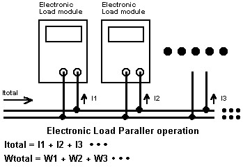
When the
Current/Watt rating exceeds the Plug-in unit rating.
Two or more
Plug-in units may be paralleled to increase the power rating. Different
electronic load modules (such as a 3310 and a 3320) may be paralleled
together.
Delete short key of Electronic Load is
recommended for parallel operation.
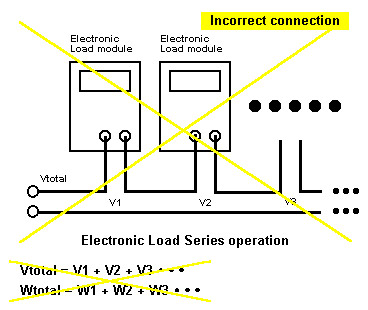
Prodigit strongly
advises against series wiring of Electronic Loads.
 2.
Vsense and Imonitor
connection
2.
Vsense and Imonitor
connection
Due to the large changes of load current will cause a voltage drop on the conductor, the Vsense input BNC is designed to compensate this condition. Prodigit 3310/3320 series Electronic Loads are equipped with Auto-Vsense capability. The DVM will measure Load input binding post when Vsense BNC to clip cable is not used. The DVM will measure the power supply output terminal voltage when Vsense cable is used, the connection diagram is shown below:
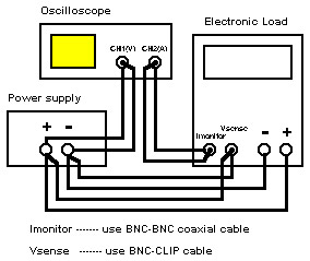
Imonitor BNC output is used to monitor the load current flow through the Electronic Load,Imonitor output is 10V F.S for Prodigit 3310/3320 series, it is normally connected to an oscilloscope for dynamic current wave form monitor, the Imonitor signal is opto-isolated to Load input common for 3310 series Electronic Load, this can eliminate the Ground loop when connects to an oscilloscope, because the Ch1 and Ch2's common on an oscilloscope is connected(not a diffential input).
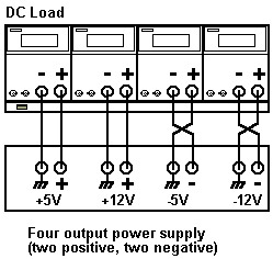
3. Multiple output (both +/-) power supply testing connection:There is a rule for connection between a multiple output power supply and a multi-channel Electronic Load: Rule: The potential of Electronic Load's positive input (Red binding post) must be higher than the Negative input (black binding post