
Application Notes-306
3250 Series AC & DC Electronic Loads - Application Description
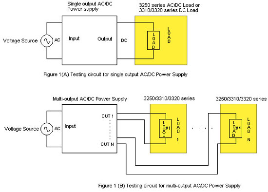
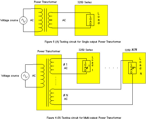
Figure 1 Example of AC & DC Power Supply Testing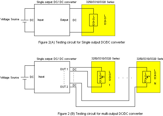 Figure 2
Example of DC & DC converter testing
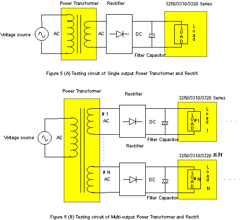
Figure 2
Example of DC & DC converter testing
1. AC
Operation
When
testing an AC either constant current or constant resistance modes may be
used.
1.1 Constant Current
Operation Mode
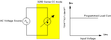
1.1.1 When selecting the constant current mode, the load current will remain
the same whether the AC source voltage fluctuates or not. (See figure 6)
1.1.2 The constant current mode may be used for AC source load adjustment or source capacitance testing. These functions may be programmed via the GPIB, RS-232C interface.
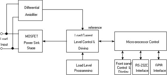
1.1.3 With a constant current, the loads needs to be set to match the input AC source frequency in order to assure load current and voltage are in the same phase. The 3250 series loads have the capability of detecting zero crossing and input load wave form. There are five different Crest Factor (peak value) current wave forms suitable for testing input voltage peak current capability: 1.414, 2, 2.5, 3.0, and 3.5. Please see the following block diagram.
1.1.2 The constant current mode may be used for AC source load adjustment or source capacitance testing. These functions may be programmed via the GPIB, RS-232C interface.
1.1.3 With a constant current, the loads needs to be set to match the input AC source frequency in order to assure load current and voltage are in the same phase. The 3250 series loads have the capability of detecting zero crossing and input load wave form. There are five different Crest Factor (peak value) current wave forms suitable for testing input voltage peak current capability: 1.414, 2, 2.5, 3.0, and 3.5. Please see the following block diagram.
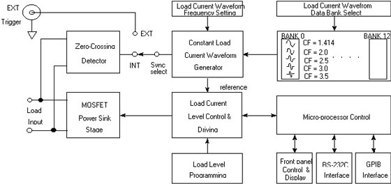
Figure 7 Block diagram of CC mode operation
1.2 Constant Resistant Operation Mode
1.2.1 When a 3250 series load is connected to an AC source (as shown in
figure 8) in the Constant Resistant (CR) mode, its load current setting is
directly proportional to the voltage, which means load current and voltage
increase at the same time.
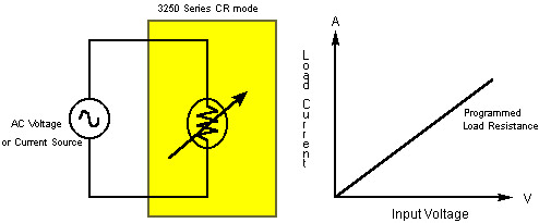
1.2.2 The constant resistance operation mode may be used for over current start testing or AC power start up. While it can also be used for testing load adjustment rates or power capacity the power source output voltage will decrease as the current increases. Voltage and current should be recorded at the same time in order to calculate the change rate, which is different from the constant current mode previously discussed as having a stable load current where it is only necessary to record the voltage for the change rate.
1.2.3 There is no need to set these units in the constant current mode because the electronic load current wave form reference source is a voltage wave form. (Please see diagram below)
2. DC Operation
The
3250 Series has two DC operating modes, constant current and constant
resistance
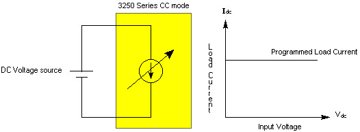
2.1 Constant Current Mode
Refer to 1.2.1
substituting 'DC source' for 'AC source'. With a DC voltage input the
frequency should be set at 0 Hz for straight load current wave form; if set
at 50 or 60 Hz the load current wave form will resemble a 50 or 60 Hz
voltage wave form. Please refer to figure 10.
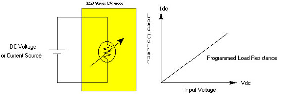
Refer to 1.2.1 substituting 'DC source' for 'AC source'. Please refer to figure 11.
3. Other Operation Features
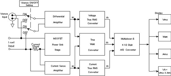
3.1 Electronic Meter
This series comes equipped with 3 AC & DC RMS electronic meters: voltage,
current and power meters. A VA meter displays capability (by multiplying
voltage by current). The data provided by these four meters provides
accurate and complete AC & DC measurements, there
is no need for additional switch settings. New data will be provided every
0.5 seconds. As these units display two pieces of data at a time, the V/A/W
button will display either V A or
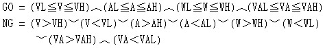
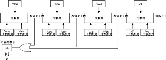
This series has upper limit and lower limit measurement comparison function capability. When the measured value is between upper and lower limits it is a GO or pass. Outside these limits the reading is a NG or fail and the NG L.E.D. will light up to indicate there is a failing condition. Measuring values include voltage, current, watt and VA; each has its own upper and lower limit and all values must be within the proper limits for the tested unit to pass. This series' displays only show an NG L.E.D. When using logic symbols, results will be as follows:
3.3 Load ON/OFF
A front panel button is used to control the load ON/OFF function. When the
LED is illuminated the load on function is activated. CC or CR modes may be
preset and will absorb the power through the loads. Changing load setting
will change the current wave form. When the LOAD button is OFF the loads
will stop loading work and the current meter will show 0 ampere. Regardless
of whether the load is ON or OFF, source voltage can still be read.
3.4 V Sense ON/OFF
Voltage sense on is activated with a front panel switch and on status is
indicated by its illuminated LED. The 3250 V Sense connector is connected to
the unit under test for measurement control. V Sense internal block diagram
is shown in Figure 12. V Sense ON/OFF control are
from load input, and related measurements may be read on the front panel
volt meter when in the constant current mode. Constant current zero cross
sensors are not used in a DC voltage application.
3.5 Setting for Constant
Current Operation Mode
When in the constant current mode it is necessary to press the Frequency
button in order that the wave form bank will synchronize with the signal
source (SYNC ON/OFF).
3.5.1 Frequency
In the constant current mode for an AC application, synchronization of the
internal wave forms generated is required to obtain the relative positions
of voltage and current. This series’ specification is 0 Hz (DC), 10 Hz - 400
Hz (AC); actual setting ranges are 0.0 Hz - 99.9 Hz, and 100 Hz - 999 Hz.
Adjustments can be made at 0.1 Hz or 1 Hz intervals.
3.5.2 Wave Form Bank
In the constant current mode, there are five peak current options: 1.414,
2.0, 2.5, 3.0, and 3.5 (see figure 7). These are stored in 1 of 12 internal
wave form banks. 55 additional wave forms can be set. EPROM memory is used
to store this information, it is stored digitally and a D/A converter
is used to convert to an analog wave form.
If the preset wave forms in the constant current or the constant resistance modes do not meet specified requirements, unique wave forms had been created. Refer to the 3250 Series Operation Manual for more Crest Factor, Square, and Step wave forms.
3.5.3 Synchronize Signal
Source
AC operation in the constant current mode requires synchronized signals in
order to synchronize voltage and current wave forms. The synchronize source
has internal Off, or external On options.
This series has an internal self synchronizing mode. When set in the SYNC Off position, the internal zero crossing sensor will recognize a wave form zero crossing signal and convert it to a square wave. This signals the internal wave form generator to force synchronization. As a result, load current wave form is related to voltage wave form.
If the voltage wave form is incorrect, this internal synchronization will not occur. In this case, external synchronization should be used otherwise only constant resistance can be used to synchronize load current and voltage wave forms. User should provide a square wave that synchronizes with the voltage to the mainframe BNC input, and set module SYNC to On in order for the constant wave form generator to synchronize with the external signal source.
4. Making A Selection
4.1 Selecting A Load Module
The 3250 Series consists of part numbers 3250 (60V/20A/300W), 3251 (150V/8A/300W), and 3252 (300V/4A/300W). Select the load that meets your voltage and current requirements. Higher accuracy is achieved when the module selected has a current rating closest to the application. If the power rating exceeds the power of a single module it is possible to parallel additional modules to achieve the power requirements.
4.2 Selecting a 3300 Series Mainframe
4.2.1 When a single module will satisfy the testing requirements, the 3302 electronic load mainframe would be the best choice. If requirements are expected to expand, a 3300A should be considered as up to three additional modules may be added as required. Blank panels may be purchased in the interim. Both the 3302 and 3300A can be purchased with or without a GPIB interface.
4.2.2 The 3300A mainframe accepts up to four 3310 and/or 3250 electronic load modules, in any combination. For a multi or mixed load requirement this is the best choice.
4.2.3 The 3300A and 3302 mainframes can be paralleled. There is no limit on the number of mainframes/modules that can be connected in parallel.